Modelling built on first-principle physics, run at production scale.
Every model we deliver traces back to the governing equations of multiphase, multicomponent flow in porous and fractured rock — not a black box. We calibrate against field observations, then push the model through HPC-scale ensembles to quantify what we don't yet know.
From digital model to resource assessment.
Digital Model
3D geological model in Leapfrog — lithology, structure, clay-cap and fault geometry, built from surface geology, well data and geophysics.
Reservoir Model
The geological model discretised into a numerical simulation mesh, with rock properties assigned per unit.
Natural-State Matching
Calibrated against observed pressure, temperature and chemistry until the unperturbed model matches the real field.
Uncertainty Quantification
An ensemble of accepted natural-state realisations spanning the plausible parameter space, not a single best-fit model.
Resource Assessment
Automated well siting, pump sizing and production forecasting across the full ensemble — P10/P50/P90 output, not a point estimate.
Numerical reservoir modelling
Finite-volume, integral-finite-difference simulation of non-isothermal multiphase flow — natural-state calibration through decades-long production forecasting, in both single-porosity and fractured dual-porosity formulations.
Parallel computing
Production and exploration models are run as MPI-parallel ensembles across NeSI, AWS and Azure HPC infrastructure, turning multi-day single runs into same-day scenario comparisons.
Uncertainty quantification
Permeability, porosity and boundary conditions are treated as distributions, not point estimates — ensemble and history-matching methods translate geological uncertainty into a defensible resource-risk range.
Software & tools
Waiwera and TOUGH2 for the core physics, run through the Geothermal Modelling Framework (GMF) developed by O'Sullivan et al. (2023) for mesh generation, automated calibration, and post-processing.
What the simulator actually solves
M — mass/energy per volume · F — flux across face Γn · q — sink/source · k — permeability · kᵣβ — relative permeability
Real figures from our in-preparation resource assessment paper
Drawn directly from our Tecuamburro–Infiernitos combined resource assessment manuscript (in preparation, not yet peer-reviewed) — the digital-to-reservoir modelling step and the pump-sizing safety margin behind the case study below.
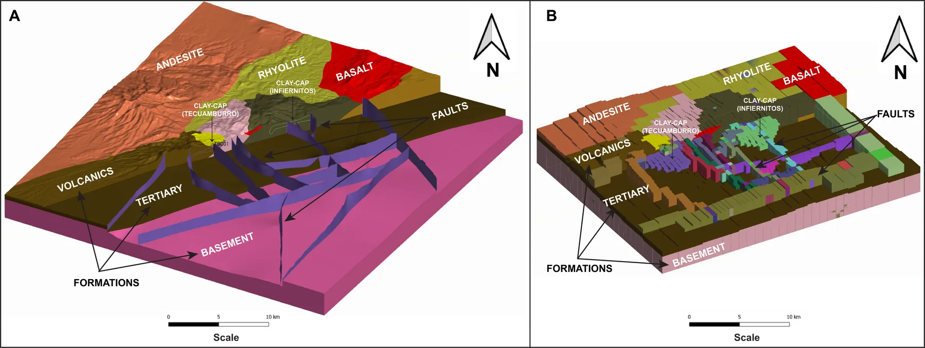
Fig. — (A) Leapfrog geological model. (B) Numerical reservoir simulation mesh, same volume.
Geological model to reservoir model
(A) The 3D geological model in Leapfrog — lithology, structure, clay-cap and fault geometry. (B) The same volume discretised into the numerical reservoir simulation mesh, with rock properties assigned per unit — steps 1–2 of our process, made concrete.
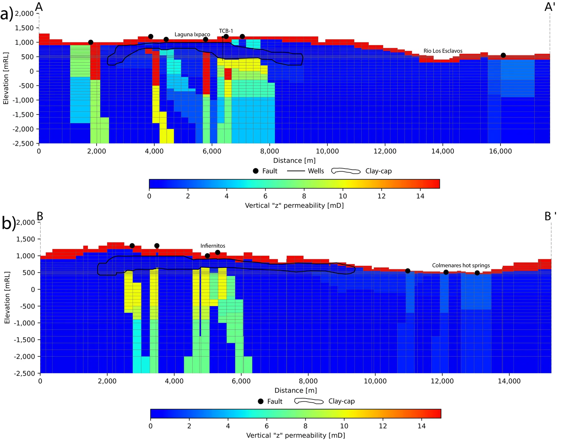
Fig. — Calibrated vertical permeability cross-sections, Tecuamburro (A–A′) and Infiernitos (B–B′).
Calibrated vertical permeability structure
Once the model is calibrated against observed pressure, temperature and chemistry, we can cut a cross-section through it anywhere — here through Tecuamburro (A–A′) and the neighbouring Infiernitos resource (B–B′), showing clay-cap geometry, faults and well locations alongside the calibrated vertical permeability.
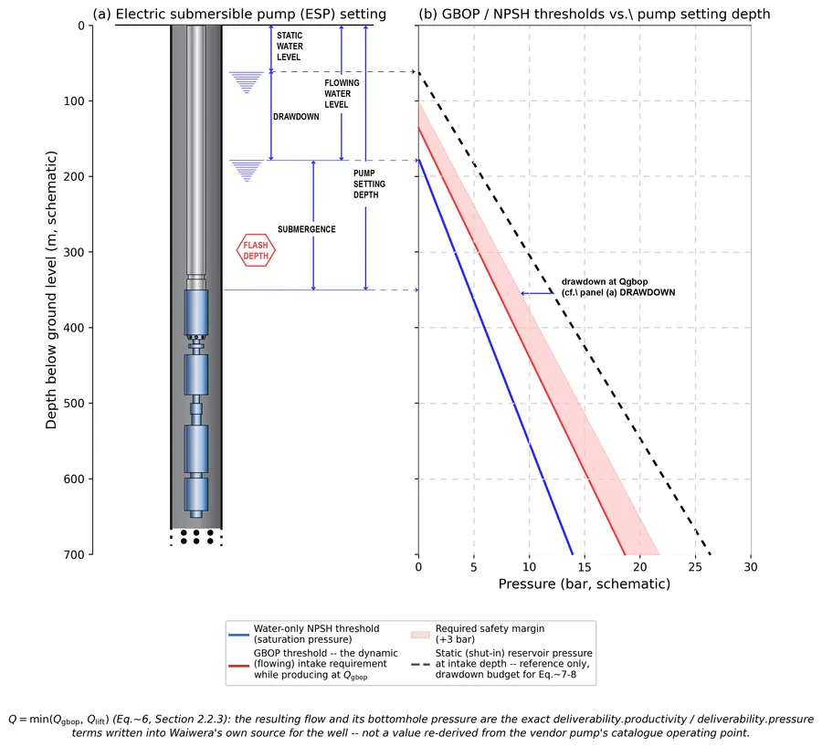
Fig. — Electric submersible pump (ESP) completion, sized against the GBOP threshold.
Two-tier pump sizing under gas-breakout pressure (GBOP)
For CO2-bearing geothermal fluid, dissolved gas comes out of solution before the fluid reaches its own boiling point — a water-only NPSH threshold under-protects the pump. We size to GBOP (saturation pressure plus the fluid's own NCG partial pressure) plus a fixed safety margin, evaluated automatically for every candidate well, then matched against a real vendor pump catalogue — line-shaft or electric submersible, up to 30 stages — for a buildable specification and its parasitic shaft power.